kilowatt-hour kWh
If you have ever looked at your home electricity bill, (and once you are in a flat, you will look extremely closely at it), the bill is composed of sections operating under different tariffs. Each meter in the meter box is driven at a rate proportional to the current passing into the house through the wiring allocated to the meter. The major electrical devices in the house such as stove, groups of power points, lights, are each allocated a meter. The meter is calibrated in "units" which are actually kilowatt-hours, a convenient measure of energy used by the power companies.
1 kWh = no. of kilowatts
turned on in the house x no. of hours
eg Your 2.4 kW heater running for 3 hours means you have to pay for 7.2 kWhr. At a tariff rate of, say, 10 cents per unit, your heater bill will cost 72 cents! That's why Mum insists you turn off unnecessary appliances around the house. (How many times have you left the heater on in your room?)
1 kWh = 1000 watts x 3600 seconds = 3.6 million joules of energy
Internal Resistance
All electrical things have some resistance (with one exception - superconducting devices), even the wiring that we have conveniently ignored and the meters and the power source (generator, battery... ).
What is the effect of this on our circuits?
Remember, resistance means energy loss; heating, light, sound or whatever.
The wiring in our circuits
- The slight resistance of our wiring becomes a significant problem if we attempt to pass large currents through the circuit. The larger the current in the wire, the more heat generated where we don't want it and by V = IR, the larger the voltage that appears across the ends of each wire itself. If the source is of fixed potential difference, the PD across the our compact disc player or whatever drops. It won't work well.
For this reason, wiring in the house is designed to work up to a maximum of 10 A or 15 A. Draw more current than this and the wiring will tend to overheat leading to a breakdown in the insulation and creating fire hazards in the walls and ceilings of your house. Fuses are designed to melt at currents above 10 or 15 A depending on their rating. Extension cords longer than a certain length must be of a higher current rating than standard.
Jumper leads for starting intransigent cars are rated at 50 A or 100 A. Choose the 100 A, much lower internal resistance, hence the donor car's full voltage willbe applied to your poor old engine.
This is also the reason why the Hydro transmits its energy at high voltage over long distance. Power = VI, so for a certain power transmission, high V means low current, the transmission lines will not heat up unnecessarily with small currents. Of course no one wants household things to operate at 200 000 volts so transformers change the energy the energy back down to low voltage, high current.
Meters
Meters automatically have some internal resistance. (How else can they give a reading?) However, a perfect meter should not affect the circuit in which it is placed.
Ammeters are placed in series so should have virtually no resistance, like wiring.
Voltmeters are placed in parallel so should have near infinite resistance so no extra current is added into the circuit. Cheap modern digital voltmeters have an internal resistance of about 50 MΩ. Very expensive voltmeters used where currents are truly tiny eg in biological cells, may have internal resistances of 300 MΩ or more.
Batteries (and generators)
These have chemicals as conductors inside. These chemicals are no where near so good conducting as copper. This means that the more current required, the more internal energy loss occurs. This shows as a voltage drop on the outside terminals. We notice the effect of internal resistance in a battery of a car at night when, if the lights are left on, we start the car. The lights dim or "go out". The starter motor draws such a large current that the terminal voltage drops well below the nominal 12V dimming the lights.
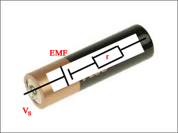
We can model a battery or generator as below
The theoretical PD produced is called the "electromotive force" the EMF, ε . This is a term from the early C19th. This is produced across the terminals when the current is zero!
The PD at the terminals, Vs = ε - Ir where I = current flowing.
As can be seen, the more current the lower the PD outside. Lots of lights in parallel will lower the PD so much that each will be dim compared to one alone. This is a BIG issue for a car battery on a cold morning.
The difference between a "flat" battery and a good one is its ability to provide current under demanding conditions, ie when a low resistance is placed across the terminals. This turns out to mean that the internal resistance of the flat battery is high while the good one is low. The chemical changes that has gone on to give a current for a long time have finally run their course and the product chemicals have a high resistance.
eg. A battery of EMF 9V has an external resistance of 5 Ω connected to it. Its internal resistance is 2 Ω What will be its delivered current and its terminal voltage?
Solution. The total effective resistance, using the above model, is (2+5) Ω because the internal resistance is in series with external circuit.
Thus, the 9V "perfect" battery produces current into 7ohm resistance.
Thus the current throughout the entire circuit,
I = V/R = 9/7 = 1.3 amp
close enough.
The external part of the circuit will have a PD of
V = IR = 1.3 x 5 volt = 6.5 volt
A voltmeter placed across the terminals will read 6.5V. 2.5 V is "lost" internally!
Imagine in the above case if the 5ohm resistance is a globe designed for 9V! It would be very dim. The battery is "flat" as far as the globe is concerned.