Wavelengths of line spectra and the Diffraction Grating topics
An alternative to a prism for observing spectra is a “Diffraction Grating”. Its disadvantage is that the image is not as bright as a prism’s BUT wavelength can be measured directly with it in conjunction with a spectroscope. This works very much the same way as a two source interference system and the final formula is the same!
Older diffraction gratings are usually optically flat, high transparency glass sheets with thousands of precision ruled vertical lines scratched on it with a diamond tip. The areas of importance are the left over flat areas, NOT the scratches. Many modern designs exist with asymmetrical lines and/or curved surfaces. Designs can use reflection instead of transmission in which the surface is a reflector with scratches creating nonreflecting areas. CDs often act as reflection diffraction gratings leading to the characteristic rainbows on their surfaces. ( Thin film interefence is also often seen on CDs.) The areas between their spirals of pitting act as the flats. CD and DVD players also incorporate a diffraction grating between the laser and disc both for reading and, using the first order patterns, tracking correction.
The unscratched areas act as slit sources. The way the grating works is that if coherent, collimated ( “made parallel” ) light falls on the grating, each flat area emits light like a slit. For angles such that the path difference to a distant screen or observer from ADJACENT flat areas, is a whole number of wavelengths, CONSTRUCTIVE interference occurs. This is from EVERY flat area, so an antinode of the particular wavelength occurs along this line.
The condition is met for only a couple of angles – called the FIRST and SECOND ORDER images - symmetrically placed around the centre line. When the path difference is zero ( zeroth order ) all the colours coincide to give a no information. When the path difference between sources is either λ or 2λ then constructive intereference leads to line images that are very sharp and angles that are easily measured. For essentially all other angles, light emitted from a particular flat is cancelled by the light emitted from some other flat area or a combination of areas – a node occurs at all other angles. ( See animation )
The simple condition gives the Diffraction Grating Formula
nλ = d sin θ where n = order = 0, 1, 2, 3 .. d = distance between rulings
For a grating of 15000 lines per inch = 15000 ÷ 0.0254 lines per metre,
d = 0.0254 ÷ 15000 = 1.693 x 10⁻⁶ m
( Many school diffraction gratings have been ruled on old "Imperial" machines where the inch still holds. The first good gratings were made in the late C19th by Rowland who used a diamond tip to cut the surface of the glass and a key precision screw thread which drove the drawing table.)
The total interference pattern of all the slits - the antinodes in directions given above is also controlled by the diffraction pattern of one individual slit! This pattern's strength is multiplied by the strength of the pattern above so the brightness of the second and third order are far less than the first order or for the straight through light. By careful design of the slit widths and shape of the emitting surfaces, light can be directed essentially into one order on one side.
Diffraction grating like patterns can be observed under ordinary circumstances. Sometimes we see "rainbows" through our eyelashes and eyebrows when looking at distant light sources and at night, distant street lamps can give diffraction patterns when observed through fine gauze curtains.
Diffraction gratings are essential in astronomy for analyzing star and galaxy spectra to elucidate the elements present and temperatures and pressures.
Holograms can be thought of as highly irregular, complex, diffraction gratings.
Phased array radar systems
Modern military radars whether naval or early warning or aircraft are moving away from parabolic dishes for the emission and detection of pulses of radio waves. They use a technology, also used by astronomers, of connecting multiple antennae to look in different directions. In essence it is a 2D diffraction array transmitting and receiving using time differences between the various antennae to change the angles of the antinodal lines.
![]()
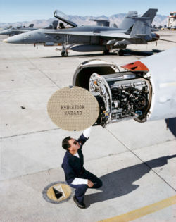
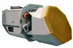
The above are an Early Warning Radar, an APG-73 Hornet radar and its replacement APG-79 radar. Aegis class frigates have similar arrays to the first photo on either side of the bridge structure. The flat areas are covered with antennae that have computer controlled emissions.
Antennae can act as emitting sources as well as receivers with equal ability. Suppose two radio transmitters/ receivers exist as in the Young's Experiment. Then, for an angle which is an antinode for emission, if we consider parallel waves coming back along that same line - they will constructively reinforce at the transmitter/receivers. Lines of strong emission will also be lines of strong reception.
By introducing time delays ( phase delays ) between antennae ( sources ) sending the same signals, we can manipulate the lines of nodes and antinodes.
If we use thousands of sources ( antennae ) over a surface, they will act as 2D diffraction gratings and antinodes will be set up in certain directions as above. Introduce phase delays between the antennae using computers to time the emission of the signal waves and we can steer these antinodes.
The resulting radars can then look at nearly the whole forward sky almost continuously without relying on mechanical scanning with breaks between actual contact with a target - potentially fatal if a missile coming towards you!